If it is used a transformer that can deliver 4a to 5a at a voltage between 126v and 16v then we can get rid of the switch for 6v or 12v batteries. No doubt about it.
The circuit is nothing but a 12v dc power supply with an ammeter for monitoring the charging current.

You can find out more Diagram below
Car battery charger schematic circuit diagram. In this circuit there is facility for monitoring the charging current and voltage. I need a circuit diagram of long range mobile jammer. Not using ics and complicated devices.
12v car battery charger circuit schematic. The transformer t1 steps down the mains voltage and diodes d1d2 does the job of rectification. This circuit has a maximum 2 amperes charging rate.
36 volt cell phone battery meter. This is a simple car battery charger with indication. Please help if any have idea about this.
This ac voltage is rectified and filtered to obtain an unregulated dc voltage used to charge the battery through a relay. This circuit can be used to charge all type of 12v rechargeable batteries including car batteries. The circuit will charge automobiles batteries without removing them from their original mounting and no need of.
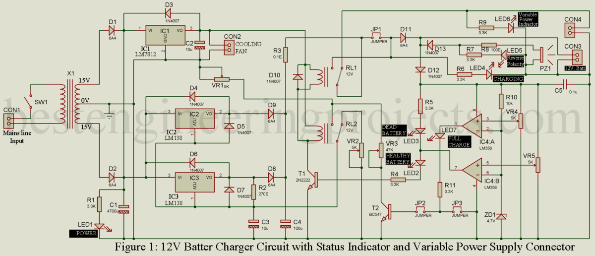
Description h ere is the circuit diagram of a simple and straight forward 12 v battery charger circuit with diagram. We use the concept of the circuit. Circuit diagram of automatic battery charger this automatic battery charger circuit is mainly involves two sections power supply section and load comparison section.
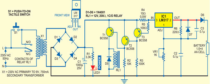
12 volt car battery charger circuit schematic. The main supply voltage 230v 50hz is connected to the primary winding of the center tapped transformer to step down the voltage to 15 0 15v. This will definitely help the auto professionals.
This is the first automatic battery charger circuit. Low cost universal battery charger schematic. Simple automatic battery charger circuit.
Just have to understand battery charging requirements only. Given below is a very simple circuit that can be used for charging car batteries. Car battery charger circuit working principle.
We can use this circuit for all battery. This is very nicely explained and it gives a whole idea about the car battery charger and the different circuits connected within it. Schematic of the automatic battery charger circuit.
The circuit is based on the ic mc78t12abt from freescalethe ic is nothing but a 7812 in to 3 package with 3a capacity. Mobile phone travel charger circuit diagram. As a test engineer i follow this site about all the new updates and these are excellent.
Mobile phone and ipod battery charger circuit. It is designed for 12v batteries. This is a schematic diagram of a full automatic 12v battery charger for charging the batteries of automobiles etc.
This car battery charger circuit can be used to charge 12v and 6v batteries. The battery is charged from a 230v 50hz ac mains supply. Constant current battery charger.
Sir i have final year project on switched mode car battery charger this charger can be made with or without transformer. Use existing products to use more benefits. Car battery 6v or 12v charger.
Nimh and nicd battery charger circuit.


0 comments:
Post a Comment