Of course some symptoms can tell you when a tps may be bad. The gryred wire feeds ground.
You can also find other images like images wiring diagram images parts diagram images replacement parts images electrical diagram images repair manuals images engine diagram images engine scheme diagram images.

You can find out more Diagram below
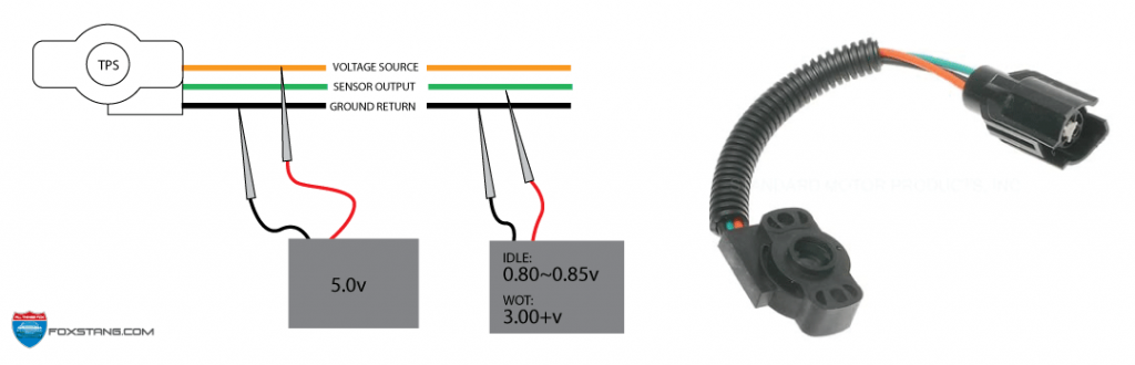
Throttle position sensor wire diagram 4. The tp sensor is a three wire potentiometer that provides an analog signal to the computer. The tps connects to the throttle plate on the throttle body. Okay ill connect you to the mechanic to go over that information regarding your toyota.
Brnwht wires feeds the tps 5 volts dc. Throttle position sensor tps wiring diagram 1997 1998 ford 46l 54l. It is a potentiometer with one end connected to 5 volts from the vcm and the other to ground.
Home repair help repair guide. Throttle position sensor tps wiring diagram part 1note. So you need to conduct some tests.
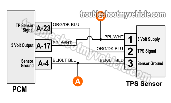
The tps needs power and ground to create a throttle angle voltage signal. A third wire is connected to the vcm to measure the voltage from the tps. Throttle position sensor test connections for 4 wire sensors.
As the accelerator pedal is depressed and released the resistance inside the sensor changes. This power is in the form of 5 volts dc and is supplied by the powertrain control module pcm. The throttle position tp sensor and accelerator pedal position app sensor are the only sensors sending data to the powertrain control module pcm that the vehicle operator has direct control over.
Throttle position sensor 4 prong here you are at our site this is images about throttle position sensor 4 prong posted by benson fannie in throttle category on oct 11 2019. Also i show you how you can figure out what each wire on your sensor is for without the use of a wiring diagram. But these symptoms may come from other bad sensors parts or components.
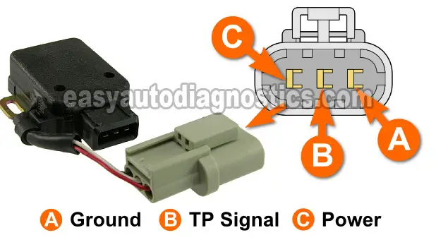
This procedure is a mute point if you have the wiring diagram but often times you just need to actuate the electronic throttle to do a cleaning. F150 f250 f350 crown victoria e150 e250 e350. The grywht wire carries the tp signal to the pcm.
When measuring the resistance arrow open and. Hi i am looking for the wiring diagram throttle position sensor plug it use 4 wires and accidentally i mix them up and i am trying to connect them back. The above tps wiring diagram applies only to 1993 1994 1995 40l jeep grand cherokee.
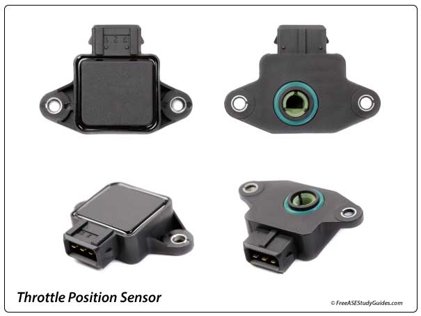
The throttle position sensor tps is connected to the throttle shaft on the throttle body. Before i do is there anything else you want him to know. Here is a quick video on how to test a throttle position sensor tps with a multimeter.
The throttle position sensor is a variable resistor. How do you know if a throttle position sensor tps is bad. Electronic throttle motor wires identification.


0 comments:
Post a Comment