Wiring for ac and dc power distribution branch circuits are color coded for identification of individual wires. In some jurisdictions all wire colors are specified in legal documents.
Electrical elements such as circuit breakers transformers capacitors bus bars and conductors are shown by standardized schematic symbols.

You can find out more Diagram below
Power line wiring diagram. In that case local custom dictates the. It shows how the electrical wires are interconnected and can also show where fixtures and components may be connected to the system. Whether you have power coming in through the switch or from the lights these switch wiring diagrams will show you the light.
A switch loop single pole switches light dimmer and a few choices for wiring a outlet switch combo device. Need a light switch wiring diagram. Disconnect ac power from the fixture.
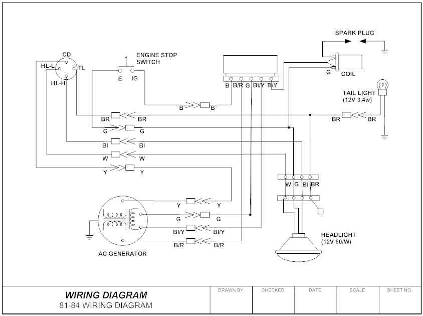
A wiring diagram is a simple visual representation of the physical connections and physical layout of an electrical system or circuit. The source is at the switch and 2 wire cable runs from there to the light. A wiring diagram is a detailed diagram of each circuit installation showing all of the wiring connectors terminal boards and electrical or electronic components of the circuit.
The source hot. However the actual look of the wiring in the box can vary depending. Single line diagram is a simplified notation for representing a three phase power system.
Select the appropriate wiring diagram to connect the emergency ballast to the ac ballast and lamp. Here a single pole switch controls the power to a light fixture. Line essentially means supply.
Light switch wiring diagram single pole this light switch wiring diagram page will help you to master one of the most basic do it yourself projects around your house. When and how to use a wiring diagram. The essence of the wiring configuration is for one hot feed wire entering the switch box to be split so that it feeds both switches which in turn feed hot wires in cables that lead out to two separate light fixtures.
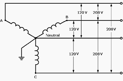
Single line diagrams sld a single line diagram shows the disposition of equipment in a substation or network in a simplified manner using internationally accepted symbols to represent various items of equipment such as transformers circuit breakers and disconnectors generally with a single line being used to represent three phase connections. In other jurisdictions only a few conductor colors are so codified. How to wire two light switches with one power supply.
This page contains wiring diagrams for household light switches and includes. Remove the ballast channel cover and install the emergency ballast either in the ballast channel see illustrations 12 or on top of the fixture see illustration 3. Instead of representing each of three phases with a separate line or terminal only one conductor is represented.
The line terminals of a gfci outlet connect to the power supply conductors that are connect at the circuit breaker or fuse box. Refer to the attached gfci outlet wiring diagram above for clarity or contact our in office electrician in mesa az free of charge. Some wiring diagrams are so large and contain so many components that the diagram is broken up into numbered and lettered sections.


0 comments:
Post a Comment